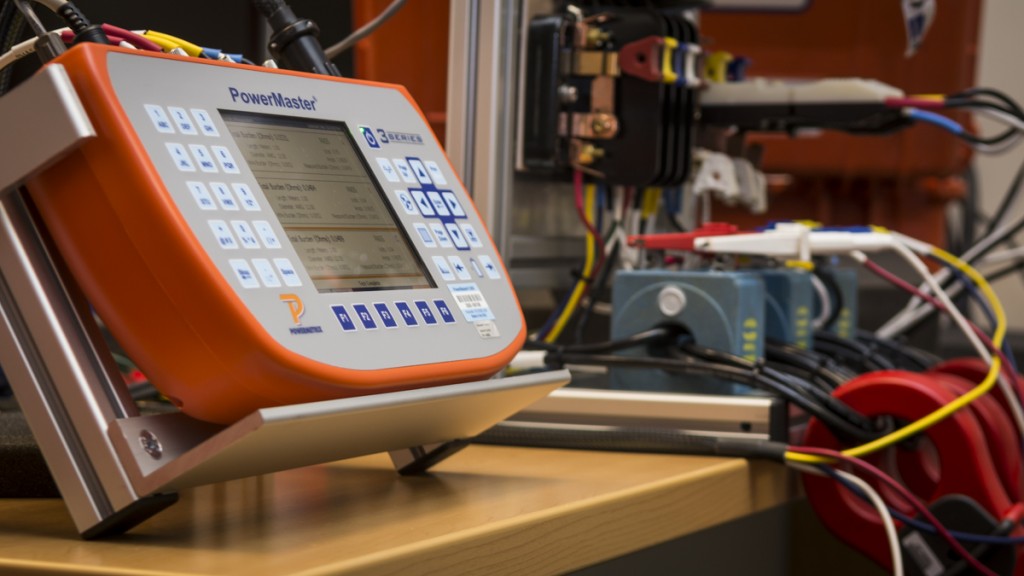
3 Series now provides simple, accurate burden measure on CTs
John Wilson plugs into the test switch, glances at the PowerMaster 3 Series screen and grins. He’s been testing CT 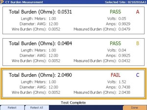 rated sites for more than a decade, but it’s never been in a true three phase manner and quite this easy. Today when burden testing the CTs, the screen says Phase A PASS, Phase B PASS, and Phase C FAIL.
“As a meterman, one of my most important jobs is to make sure the utility isn’t losing money,” Wilson explained. “When meters or CTs are failing their accuracy tests, it usually means the customer is receiving power at a bargain price. My boss doesn’t like that.”
“To try and diagnose these types of CT errors, we used to hook up separate equipment to inject extra burden onto the secondary of each individual CT and measure the secondary current change,” Wilson said. “That was not only time consuming, but required a fairly deep understanding of burden and generated a graph that was difficult to explain and left out key information.”
Powermetrix introduced a new feature for the 3 Series product line in late 2015 that solves this problem by measuring the actual burden present on the CT. In order to truly understand this breakthrough, it is important to understand how accuracy ratings are specified on CTs.
For example, a CT nameplate may show a Ratio of 200:5 with accuracy class of 0.3% while operating at 30°C and with up to 0.2 ohms of burden on its 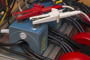 secondary. The 0.3% accuracy class of this CT is only guaranteed while the CT is at its fully rated load (200A on the primary). During a normal CT ratio
test, the primary and secondary current are always measured. It is simple to measure the temperature at the site to make sure the temperature is within the 30°C rating, but making sure the CT is within its burden rating has always been more difficult to prove.
In the past, like John Wilson described, the utility would inject extra burden into the secondary of the CT and measure the secondary current to see if and when it would decrease. This process merely simulated an overburden condition and stressed the CT to see when it failed. The most important questions were always “What was the actual burden on the CT before I added extra burden, and was that burden within its nameplate specification?” That question could never be easily answered…until now.
“The ultimate goal is to not only verify the CT is performing as expected, but that the CT was correctly specified and installed in the first place. That is simply not possible without truly measuring the burden,” Powermetrix Product Manager Eric Hubbard explained. “The old method of added burden testing generated a result that wasn’t intuitive and lacked critical information.”
Powermetrix was asked by metermen across the country if we could come up with a better, yet simple solution. Our engineering team got together and created the burden measurement testing program that is revolutionizing CT testing.
The process is as simple as measuring the voltage drop across the secondary connections of the CT while at the same time measuring the secondary current. If the secondary connections of the CT are not available, then the 3 Series allows the user to measure the voltage drop at the test switch and enter values for the gauge and length of wire from the CT to the meter.
Either way, the PowerMaster 3 Series will calculate the burden in Ohms, finally giving the utility a way to prove the CT is within its accuracy specification at verifiable loads, temperatures, AND burden. Wilson is still grinning when he sees that the PowerMaster 3 Series clearly shows the burden (Ohms) on Phase C is much higher than Phases A and B, and well outside of the burden specification. Because of his years of knowledge, he goes on a hunch, and starts tightening the Phase C connections while 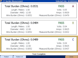 carefully following his utility’s safety protocol.
“Back in the old days, I usually could tell when there was a problem,” Wilson said. “But I never felt very confident I was fixing the right problem.”
Rerunning the CT Ratio test on the 3 Series, Wilson sees that just tightening the connections did the job.
All three CT phases now show PASS, PASS, PASS.
Learn More about CT Testing:
![]()
WIKIPEDIA: Current Transformers

Electronics Tutorials: Current Transformers
![]()
YOU TUBE: CT Electric Meter Wiring